 WATER TREATMENT FACILITIES OF
THE LAKE COUNTY PUBLIC WATER DISTRICT
The Lake County Public Water District (District) presently provides drinking water to the City of Zion, the Village of Winthrop Harbor, and the State of Illinois Department of Natural Resources. (Illinois Beach State Park). The District is always amenable to expansion if other communities are interested.
The present District’s base treatment facilities came online in 1970. Significant plant additions were undertaken in 1979, 1986, 1992, 1998, and 2008. The plant today is capable of supplying its existing customers a maximum daily flow of 6,500,000 gallons. All of the facilities are computer operated and controlled. This operational sophistication allows the plant to be controlled at all times by a three person operating staff. This means significant cost savings for the District’s customers, without any sacrifice in water quality. In fact, the District has been, and continues to be, an award winning facility.
The District prides itself on staying abreast of new developments in the field of drinking water treatment. For example, the District was the first governmental entity in Illinois to pilot test ultra-membrane filtration as a new process for the treatment of Lake Michigan water. This successful test program provides the District with first-hand knowledge of a new state of the art treatment process that will be used for any future plant expansion. This is another demonstration that the District strives to continue to be a low cost provider of high quality water to all of its customers.
Security concerns now limit the public’s access to the District’s facilities. For more information, call the District at 847-746-2052. Tours can be arranged, but only under carefully controlled procedures.
BOARD OF TRUSTEES
Chairman – Gerold L. Topcik
Vice-Chair – Michael B. Ruchti
Trustee – Douglas A. Jaeger
Trustee – Amos J. Monk
Trustee – Douglas J. Ower
Trustee – Kristine C. Smith
Trustee – Suriyya A. Latif
Secretary – Karen L. Johnston
General Manager/Treasurer – Donald J. White
INTAKE FACILITIES
The intake facilities consist of two submerged steel cones, each with an 8.5-foot diameter opening. These cones are connected to the end of a 42-inch concrete pipe 3000 feet into the lake from the shoreline of Lake Michigan. The lake is approximately 25 feet deep at this location. The 42-inch intake pipe was originally buried beneath the lake bottom with a minimum cover of 4 feet. Rock is periodically added over the pipe to maintain this cover. Other methods of stabilizing the pipe are also being used.
RAW WATER PUMPING STATION
The raw water pumping station is located near the edge of Lake Michigan east of the treatment plant. The lower level of the pumping station contains a large wet well area interconnected with the 42-inch diameter intake pipe. The wet well is equipped with a traveling water screen, and the three pump suctions. Located above the wet well at the ground level are the three low lift pumps (60 hp units), the head of the traveling water screen and the instruments and control panel for all electrical equipment within the pumping station. All low lift pumps are essentially the same size with any two of the three units capable of pumping at a six and a half million gallon day rate.
These pumps discharge raw water to the treatment works through a 20-inch raw water transmission line also approximately 3000 feet long.
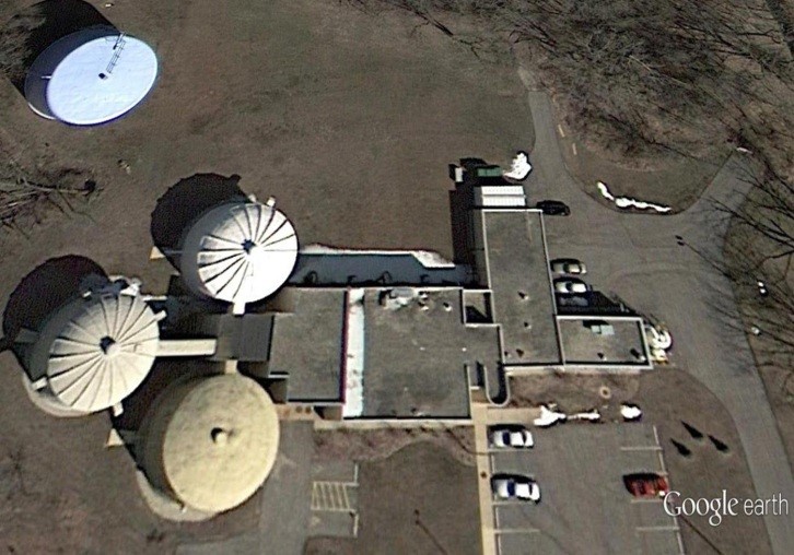
TREATMENT PLANT
The treatment plant contains the following treatment processes and supporting facilities:
- Coagulation
- Flocculation
- Clarification
- Filtration
- Water Storage
- Disinfection
- Treated Water Pumping
- Laboratory Facilities
- Computerized Process Control
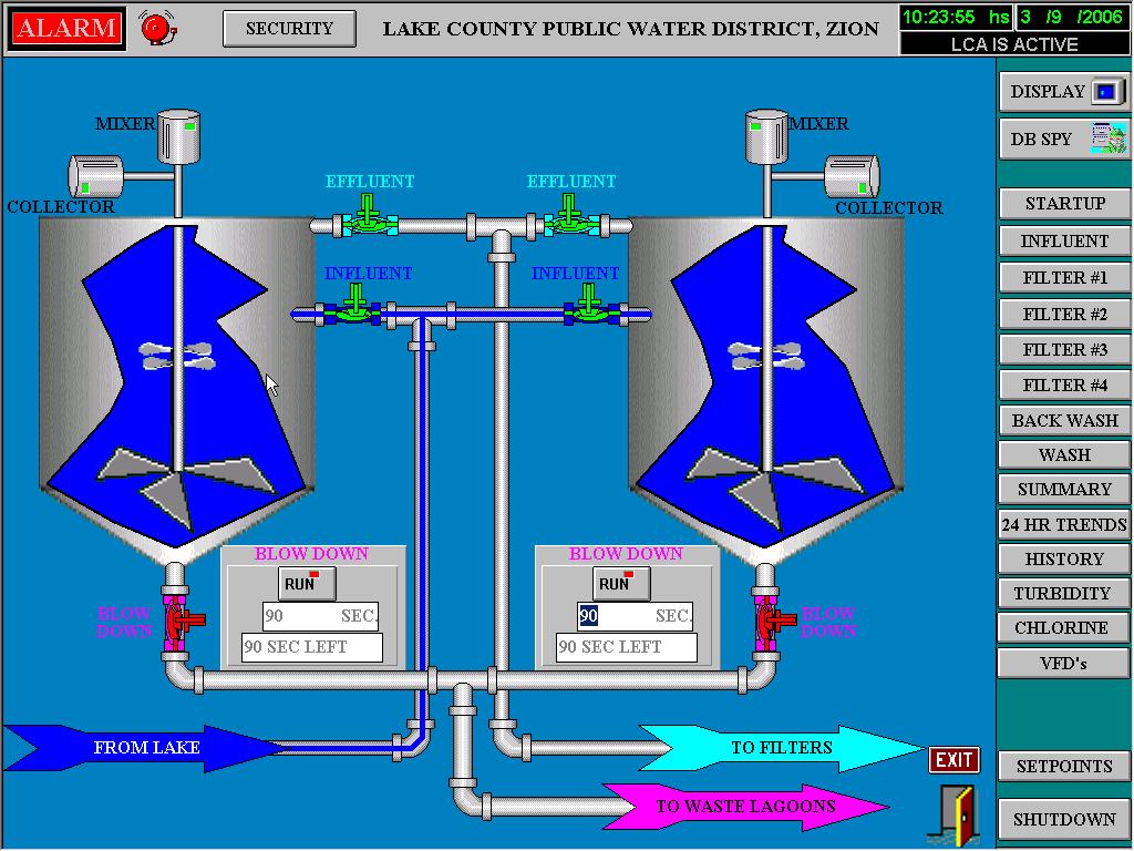
This water treatment plant can be totally operated and monitored from the control area on the second level of the filtration building. All of the operations during the treatment process are automatic.
The operation of the plant is under the control of the Operations Manager and his staff of three full-time operators. The on-duty operator maintains contact using wired and wireless services and personal computers.
1 – Coagulation
Alum is the chemical of choice to coagulate any contaminants (solids, turbidity, etc.) present in the raw water. Alum is added to the raw water feed line just ahead of a static mixing unit that leads to the first stage mixing zone in each of the solids contact units. Mixing is needed to assure blending of the alum solution and raw water to begin the formation of floc particles.
2 – Flocculation
A positively charged polymer is then added in this first stage of the solids contact units as the coagulated water moves into the flocculation-mixing zone. In this zone, under more gentle mixing conditions, the polymer “bridges” across the smaller floc particles to form larger, more settleable particles.
3 – Clarification
Treated water, containing the flocculated solids particles, flows into the settling zone of the solids contact units. In this zone, a continually decreasing velocity allows the treated floc particles to settle out. The solids contact units are designed such that some of the floc particles are continually recycled to “seed” (speed up) the initial flocculation step. Excess particles are removed from the process for ultimate disposal (to a wastewater plant).”
4 – Filtration
The settled water leaving the settling zone of the solids contact units flows by gravity to the four final filtering units. These filters, which contain coal and sand as the filtering media, remove the remaining solids particles. Periodically, one or more of these filter units is “back-washed” to remove collected solids, which again are sent to ultimate disposal.
5 – Water Storage
The treated water is now fully clarified, and meets all regulatory requirements other than final disinfection. The District has over 1,100,000 gallons of storage on site. This storage allows the District to “level out” demand for the treated water, which is particularly important during times of peak usage. Water is moved between the filtration process and storage by two transfer pumps (75 hp each). These same pumps provide water for the “back washing” process noted previously.
6 – Disinfection
Before discharging this treatment water into the District’s customers’ water distribution systems, chlorine is again added to disinfect the water. Chlorine is not only a very effective disinfectant; it also maintains a residual as the treated water moves through the various distribution pumping systems.
A compound containing fluoride is also added at this time to help reduce tooth decay.
7 – Treated Water Pumping
Three large (200 hp each) equally sized pumps are available at the plant to move this treated water from the on-site storage to the customers’ transmission and distribution systems. Any two of these three pumps can discharge treated water at up to the District’s rated peak capacity of 6,500,000 gallons per day. Actual pumping rates are established by usage levels in the District’s service area.
8 – Laboratory Facilities
The District has sufficient laboratory facilities to run all required analyses for control of the chemical feed part of the plant’s requirements. Other laboratory tests, as required, are conducted for the District by laboratories having all of the required certifications.
9 – Computerized Process Control
The District continues to provide leadership by having a “state of the art” computer based process control and data management system. This system has the capability of automatically controlling all unit processes and functions required within and without the treatment plant site. Thus, minimum operator attention is required, and the opportunity for error is minimized.
A secondary, but extremely important, attribute of the installed computer system is its data management capabilities. Data storing, sorting, and retrieval are easily accomplished with the system. This system is updated on a regular basis to enhance its overall capability.